Setting the Z axis correctly is one of the most important steps before cutting wood, plastic, or other approved materials on a CNC router. A small error can leave a shallow engraving, damage the spoilboard, or break a cutter. This guide explains how to zero the z axis on a cnc router using practical methods suited to modern machines in 2026. It covers manual touch-off, conductive touch plates, automatic probing, and tool-length changes.
Accuracy begins with preparation. Secure the workpiece firmly, clean dust from the spoilboard, and confirm that the selected bit is fully seated in the collet. A paper sheet may provide a useful manual reference, while a calibrated probe can improve repeatability. Watch the display closely. A single extra jog can change the cutting depth.
Different controllers use different zeroing commands, probe inputs, and coordinate conventions. Your machine manual remains the final authority. Never assume that a negative Z value means the same thing in every software package. That mistake is common. I have also seen careful operators trust an untested touch plate, only to discover a damaged cable after the cut began. A reliable workflow includes a slow test move, a clearance check, and a dry run above the material. The following sections examine each method, explain when it is appropriate, and identify the small habits that make Z-zero results safer and more consistent. Expect some trial and adjustment. No setup is perfect on the first attempt.
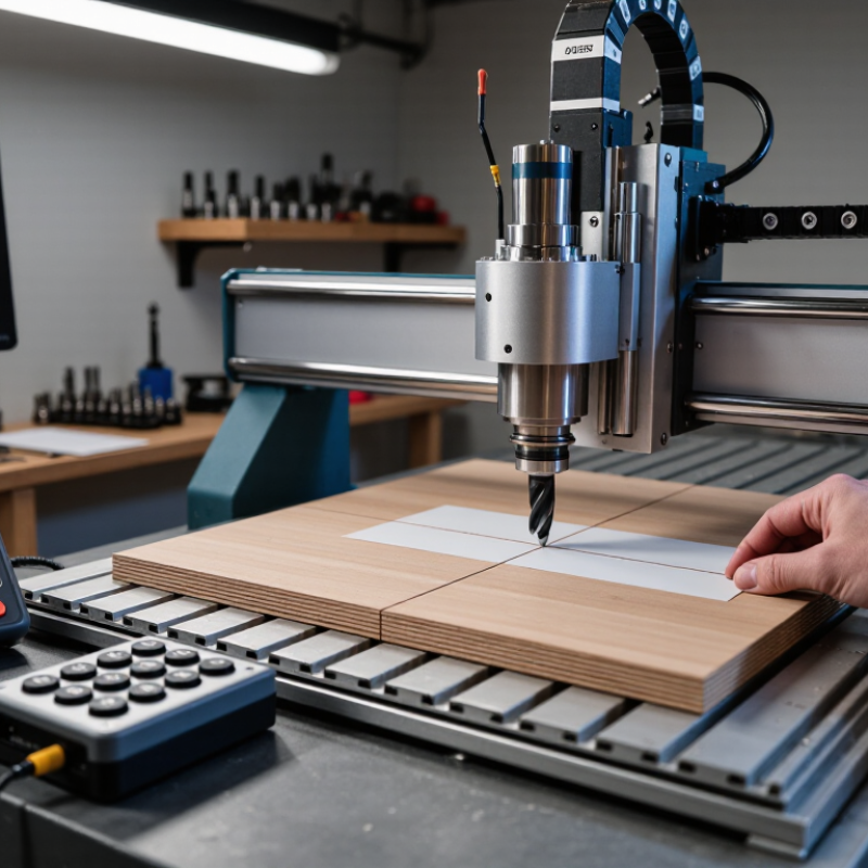
The correct Z-zero datum depends on what the cutter must reference. Stock-top zero measures every depth from the material surface. It suits carving, pockets, and variable-thickness boards. Touch the cutter lightly, then confirm the surface at several points. A bowed sheet can make one reading misleading.
Spoilboard zero references the sacrificial surface beneath the workpiece. It works well for through-cuts, because the programmed depth remains consistent after material thickness changes. Machine-bed zero is less common for daily cutting. It can help with fixtures, but only when the bed height is known and protected. Never assume the bed is perfectly flat.
I recheck it.
ISO 230-2 defines repeatability and positioning tests for machine tools, supporting repeated measurements instead of one convenient touch-off. NIST’s Engineering Statistics Handbook also stresses recording variation, not only the average reading. Take five Z readings around the work area. Record the spread. If readings differ by 0.3 millimeters, the problem may be stock flatness, gantry alignment, or probe technique. Do not hide that result.
A clean zero can still be wrong. For a 12-millimeter board, I usually verify the programmed depth with a shallow test cut before committing to a full sheet. That small scar is cheaper than a ruined panel.
A reliable Z-zero begins with preparation, not a quick tool touch. ISO 230-2:2014 treats positioning accuracy and repeatability as measurable machine characteristics. Your router should be warm, clean, and mechanically settled before measurement. Remove chips from the spoilboard and collet area. Secure the workpiece firmly. Even a thin chip can shift the reference surface.
Home every machine axis, then inspect the Z-axis movement for backlash or stiffness. Use a calibrated tool setter, touch plate, or dial indicator. Lower the cutter slowly until contact is consistent. Record the measured height. Repeat the touch-off at least three times. ISO 230-2 emphasizes bidirectional testing because approach direction can change the result. That small difference matters.
Check the machine at several Z positions, not only near the work surface. NIST Technical Note 1297 recommends reporting measurement uncertainty with coverage factor k=2, representing approximately 95% confidence. That mindset is useful here. A displayed zero is not proof of accuracy. The International Federation of Robotics reported 162 robots per 10,000 manufacturing employees worldwide in 2023, showing how production increasingly depends on repeatable positioning. CNC routers face the same expectation, even without robotic automation. I still recheck after long warmups. Sometimes the first reading looks perfect. It is not always trustworthy. Record temperature, tool length, touch-off direction, and measured variation before cutting.
How to Zero the Z Axis on a CNC Router in 2026?
A 0.01 mm-resolution probe or tool setter can make Z-axis setup faster and more repeatable. Before probing, clean the spoilboard, cutter, and sensor surface. A tiny chip can shift the reading. Confirm that the probe is firmly connected and responds in the control software. I always test the signal above the workpiece first. It prevents an expensive surprise.
Place the probe directly under the cutting tool, then lower the Z axis slowly. Use a conservative probing speed, especially with a delicate sensor. The machine should stop when contact is detected. Record the measured plate thickness and verify the offset in the work coordinate system. If using a tool setter, touch off the first tool, change tools, and measure every replacement tool at the same reference point. Do not assume two cutters have identical lengths.
Accuracy depends on more than the displayed resolution. Frame flex, temperature, dust, and an uneven workpiece can introduce error. A 0.01 mm screen value does not guarantee 0.01 mm cutting accuracy. Check the result with a shallow test cut and measure the finished step using a calibrated gauge. My early setups occasionally showed a perfect probe reading but cut too deep. The cause was usually a dirty contact surface or an incorrect offset. That mistake still deserves attention. Perform a second probe cycle when the reading seems unusual, and keep a simple setup record for future jobs.
Comparing the nominal resolution of common Z-axis touch-off methods. A 0.01 mm-resolution probe or tool setter provides a finer reference than manual paper-based touch-off.
Lower values indicate a finer nominal measurement increment. Actual cutting accuracy also depends on machine rigidity, tool runout, surface cleanliness, calibration, and the repeatability of the probing cycle.
Before probing, clean the machine bed and the workpiece surface. A single chip can change the Z reading. Measure the probe thickness with a reliable caliper, then write the value down. Do not trust a faded label or an old setup note.
Place the probe on the material and connect it according to the machine’s safety procedure. Jog the tool slowly above the probe. Lower the Z axis in small steps until the probe triggers. Keep your hand near the emergency stop. The machine should never move unexpectedly.
When the tool touches the probe, the tool tip is above the material by the probe’s thickness. Enter that measured value into the probing routine, using the correct sign for your controller. The routine should calculate the material surface and store that Z offset in G54. If entering it manually, confirm whether your control uses machine coordinates or work coordinates. This detail causes many avoidable errors.
I verify the result with a paper test and a shallow air cut. The paper should drag lightly, not tear. I once accepted a convenient rounded probe value, and the first cut was visibly too deep. That mistake reminded me to measure every setup. Check the G54 Z value before cutting valuable material, especially after changing tools or moving the workpiece.
How to Zero the Z Axis on a CNC Router in 2026?
Verify Zero with a Three-Point Check Within ±0.05 mm
Accurate Z-zeroing starts with a clean, stable work surface. Secure the material firmly, then remove dust from the cutter, spoilboard, and probing area. Select the correct tool before measuring. Tool length changes can shift the cutting depth noticeably.
Lower the tool carefully until the probe or touch plate registers contact. Set the material’s top surface as the Z reference. Now test three points: front-left, rear-right, and center. Record each reading without changing the machine coordinate system. The difference between the highest and lowest reading should remain within ±0.05 mm. Keep the test points widely spaced. A narrow check can hide unevenness.
I prefer repeating the check after a short pause. Temperature, loose clamps, or a slightly tilted plate can alter results. I once accepted a single-point reading that looked perfect, but the rear corner cut too deeply. The problem was not the zero setting; the spoilboard was uneven. If the three-point readings exceed tolerance, inspect the spoilboard, gantry alignment, probe seating, and material movement. Clean contact surfaces again and repeat the measurement. A shallow test cut across all three areas offers another useful confirmation. Watch the cut edge closely. Uneven depth usually tells the truth.
Z-zero is the reference height for cutting depth. Every programmed vertical movement depends on this position.
Use stock-top zero for carving, pockets, and boards with uneven thickness. Touch the cutter lightly against the surface. Check several points.
Spoilboard zero suits through-cuts. It keeps the cutting depth consistent when material thickness changes. Protect the spoilboard from excessive cutting.
Machine-bed zero is less common for routine cutting. It can support fixtures when bed height is known. Never assume the bed is flat.
Warm the machine and clean chips from the spoilboard and collet. Secure the material firmly. Home every axis first.
Take at least three touch-offs. For better records, take five readings around the work area. Record the highest and lowest values.
Check the front-left, rear-right, and center points. Keep their difference within ±0.05 millimeters. Wider spacing reveals more unevenness.
It may indicate stock flatness, gantry alignment, probe seating, or measuring technique. Do not hide the variation. A clean zero can still be wrong.
Yes. For a 12-millimeter board, make a shallow test cut first. Inspect all three areas. A small scar is cheaper than a ruined panel.
Temperature, loose clamps, and tilted material can change the reading. I still recheck after a long warmup. My first reading is not always trustworthy.
This guide explains how to zero the z axis on a cnc router with a repeatable, accuracy-focused workflow. Begin by choosing the correct Z-zero datum for the job: the top of the stock, the spoilboard, or the machine bed. Prepare the router carefully, checking that the table, gantry, and tooling are clean, secure, and properly aligned. Use ISO 230-2 positioning-accuracy principles as a practical reference for consistent machine preparation and movement checks.
Next, touch off the tool with a probe or tool setter offering 0.01 mm resolution. Account for the probe’s thickness or trigger height, then enter the calculated offset into the G54 work coordinate system. Finally, verify the result with a three-point check across the working area. If the measured values remain within ±0.05 mm, the Z-zero is suitable for accurate cutting. Recording the datum and verification results can also make future setups faster, more consistent, and easier to troubleshoot.

AcuTek CNC